原文地址:https://www.laroberto.com/remote-lan-access-with-wireguard/
本文中,让我们来看看如何使用WireGuard建立一个简单而安全的隧道(VPN)到你的本地局域网(homelab)。我们将采用VPS的方式,这样我们就不必向互联网暴露任何端口。
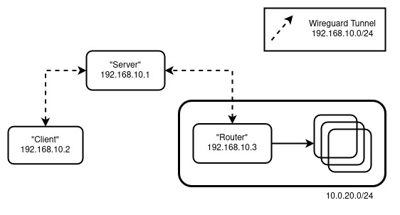
我们将模拟以下设置

角色:
- Router - 将作为你的局域网网关(向内)的机器。
- Server - 具有公网IP的机器,所有客户将连接到它,也被称为Bounce Server。
- Client - 你,试图在某个地方远程连接到局域网。
配置 #
注意:所有的机器都基于 Ubuntu,根据你选择的 Linux 发行版调整设置
Server 和 Router #
对于Server 和Router执行以下操作
sudo apt update && sudo apt upgrade
sudo apt install wireguard
wg genkey | tee privatekey | wg pubkey > publickey
sudo sysctl net.ipv4.ip_forward=1
注意:要持久化 IP 转发,编辑 /etc/sysctl.conf,添加 net.ipv4.ip_forward=1
对于Server,创建 /etc/wireguard/wg0.conf:
[Interface]
Address = 192.168.10.1/32
ListenPort = 51820
PrivateKey = <Server's Private Key>

# Router Peer
[Peer]
PublicKey = <Router's Public Key>
AllowedIPs = 192.168.10.0/24, 10.0.20.0/24
对于Router,创建 /etc/wireguard/wg0.conf:
[Interface]
Address = 192.168.10.3/32
PrivateKey = <Router's Private Key>
PostUp = iptables -A FORWARD -i wg0 -j ACCEPT; iptables -t nat -A POSTROUTING -o ens18 -j MASQUERADE
PostDown = iptables -D FORWARD -i wg0 -j ACCEPT; iptables -t nat -D POSTROUTING -o ens18 -j MASQUERADE

# Server
[Peer]
PublicKey = <Server's Public Key>
Endpoint = <Server's Public IP>:51820
AllowedIPs = 192.168.10.0/24
PersistentKeepalive = 25
注意:根据你的接口实际情况替换 ens18
通过 wg-quick up wg0启用该接口,然后通过wg show检查状态。
在这一步,我们可以进行一次快速的检查。在我的设置中,在Server上运行 mtr 10.0.20.1 会产生如下输入
                         Packets               Pings
Host                   Loss%   Snt   Last   Avg  Best  Wrst StDev
1. 192.168.10.3        0.0%     2   61.8  41.5  21.1  61.8  28.8
2. 10.0.20.1           0.0%     2   48.3  33.0  17.6  48.3  21.7
Client #
Client 进行如下操作
sudo apt update && sudo apt upgrade
sudo apt install wireguard
wg genkey | tee privatekey | wg pubkey > publickey
创建 /etc/wireguard/wg0.conf:
[Interface]
Address = 192.168.10.2/32
PrivateKey = <Client's Private Key>

[Peer]
PublicKey = <Server's Public Key>
Endpoint = <Server's Public IP>:51820
AllowedIPs = 10.0.20.0/24
PersistentKeepalive = 25
通过 wg-quick up wg0 启用该接口,然后通过 wg show 检查状态。我们还需要更新 Server 的 wg0.conf,将 Client 作为一个新的 Peer。
更新 Server的配置内容
[Interface]
Address = 192.168.10.1/32
ListenPort = 51820
PrivateKey = <Server's Private Key>

# Router LAN
[Peer]
PublicKey = <Router's Public Key>
AllowedIPs = 192.168.10.0/24, 10.0.20.0/24

# Client
[Peer]
PublicKey = <Client's Public Key>
AllowedIPs = 192.168.10.2/32
注意:更新后别忘记重启 Server 上的 wg,命令为 wg-quick down wg0 && wg-quick up wg0
现在,在Client上运行mtr 10.0.20.1产生
                         Packets               Pings
Host                   Loss%   Snt   Last   Avg  Best  Wrst StDev
1. 192.168.10.1        0.0%     6   41.2  42.1  21.4  73.6  18.7
2. 192.168.10.3        0.0%     5   64.8  72.0  41.8  88.1  19.3
3. 10.0.20.1           0.0%     5   77.4  62.3  43.0  77.4  13.3
这符合我们想要的 Client->Server->Router 流程。
深入配置 #
大部分的路由是由 [Peer] 和 AllowedIPs 配置决定的。它规定了什么可以进入和离开隧道。例如,对于以下设置。
Peer A
[Interface]
Address = 192.168.10.1/32
...snip...

[Peer]
PublicKey = <Peer B's public key>
AllowedIPs = 192.168.10.0/24
Peer B
[Interface]
Address = 192.168.10.2/32
...snip...

[Peer]
PublicKey = <Peer A's public key>
AllowedIPs = 192.168.20.0/24
如果Peer A试图连接到(例如)192.168.10.11,由于该地址在192.168.10.0/24之内,它将被允许 进入 Peer A 的一侧。当它从Peer B那边出来时,由于它不在192.168.20.0/24范围内,它将被放弃。当[Interface]中Address含有网络掩码时(即192.168.10.1/32变更为192.168.10.1/24),就会变得有点混乱。虽然[Interface]中Address也可以影响路由(如果有网络掩码),但最终决定总是由[Peer] AllowedIPs 决定。例如
Peer A
[Interface]
Address = 192.168.10.1/24
...snip...

[Peer]
PublicKey = <Peer B's public key>
AllowedIPs = 192.168.20.0/24
如果我们试图连接到192.168.10.11,由于192.168.10.1/24,它将被路由到这个接口,但由于它不在192.168.20.0/24范围内,它将不被允许进入隧道(丢弃)。
为了进一步证明,使用我们开头案例中的设置。
将Router的 [Peer] AllowedIPs 字段从 AllowedIPs = 192.168.10.0/24 变更为 AllowedIPs = 192.168.10.2/32
此时,尽管Server已经不能访问10.0.20.1/24,但Client仍然可以访问。
将Client的 [Peer] AllowedIPs = 10.0.20.0/24, 192.168.10.0/24 更新为 AllowedIPs = 10.0.20.0/24
Client仍然能够到达 10.0.20.1/24,但是 mtr 不再显示链上主机的IP了(如下)
                              Packets              Pings
Host                   Loss%   Snt   Last   Avg  Best  Wrst StDev
1. (waiting for reply)
2. (waiting for reply)
3. 10.0.20.1           0.0%   222   41.7  47.1  37.3 180.8  15.5
原因是,当主机试图回复 mtr 时,数据包被丢弃。毕竟,Server(192.168.10.1)和 Router(192.168.10.3)不在 Client 的新 [Peer] AllowedIPs 范围内。